I decided that I had no interest in Amazon having the ability to blast adverts at me, so I turned it into (mostly) e-waste.
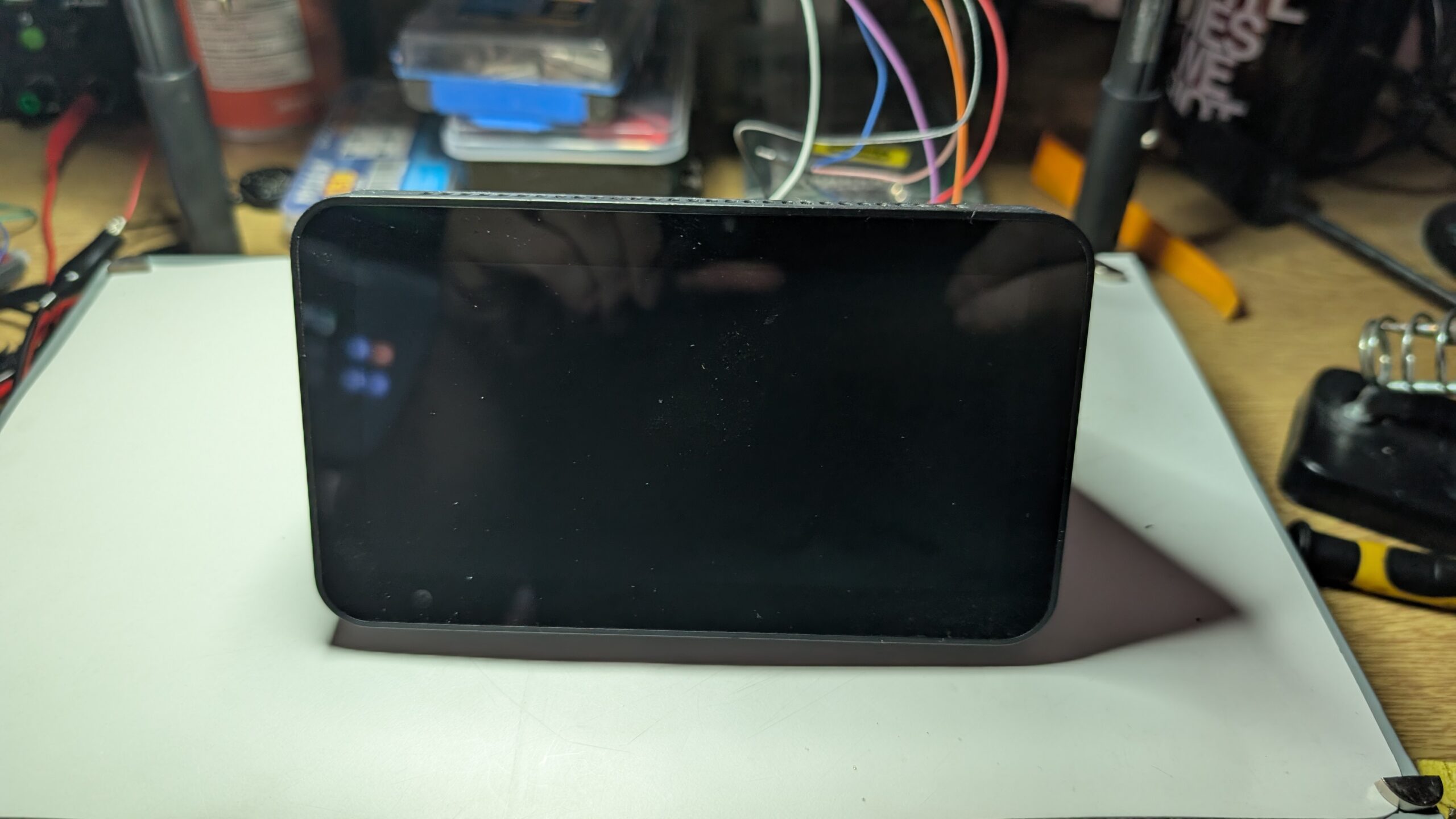
This is an Amazon Echo Show 5 Gen 2. I got it a couple of years ago. It’s useful as a way to show the weather, but I am definitely not on board with having a capitalism blasted into my face.
It had to go.
I am far from being the first person to do this, and there’s nothing here that’s new. I’m just an idiot destroying things, so if you’re trying to do something useful you should check out these too:-
- Amazon Echo Show 5 2nd Gen Smart Display Teardown [briandorey.com]
- Amazon Echo Show 5 Disassembly [ifixit.com]
Opening the damn thing

The first order of business is to get the thing open. There’s no obvious screws on the outside, which means they’re hidden. The prime suspect here is the large rubber pad on the bottom.
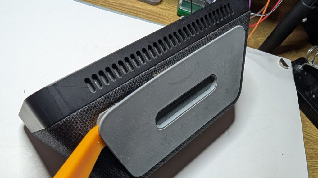
It turns out this is glued down and can be ‘encouraged’ to pop off with an appropriate spudger, revealing a set of screws.
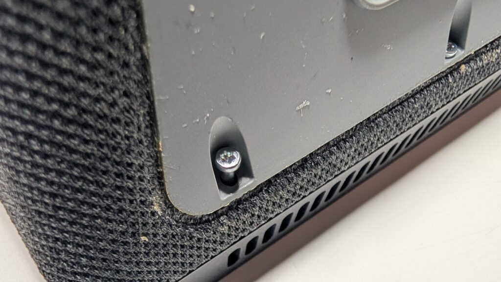
At this point I should apologise for the gunk in these close-ups. Being an uncoordinated idiot, I managed to knock over a glass of water on my desk at some point in the past few years, and the casing clearly decided to suck up whatever crap was on my desk.
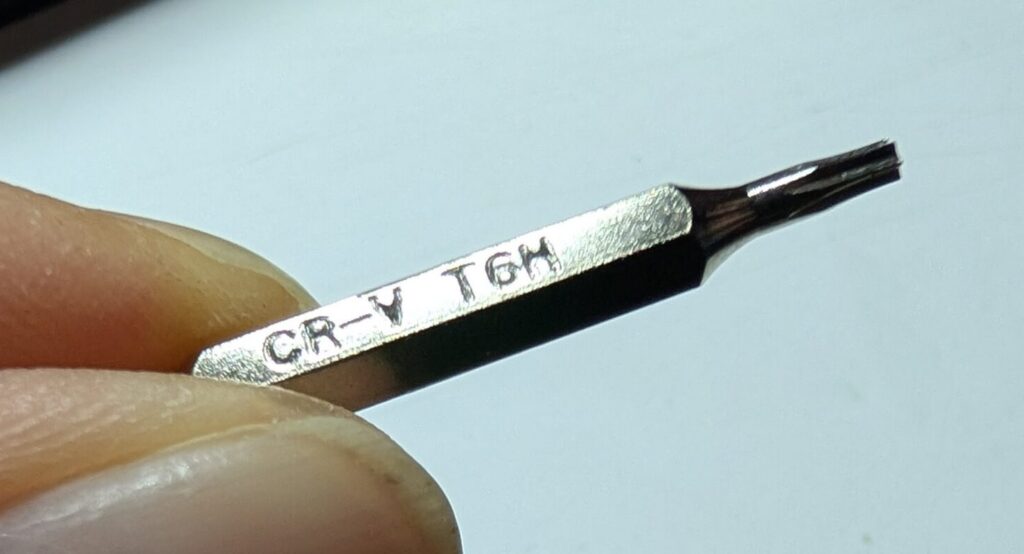
The screws seem to be a T6 Torx – this is the driver I used here.
Going in
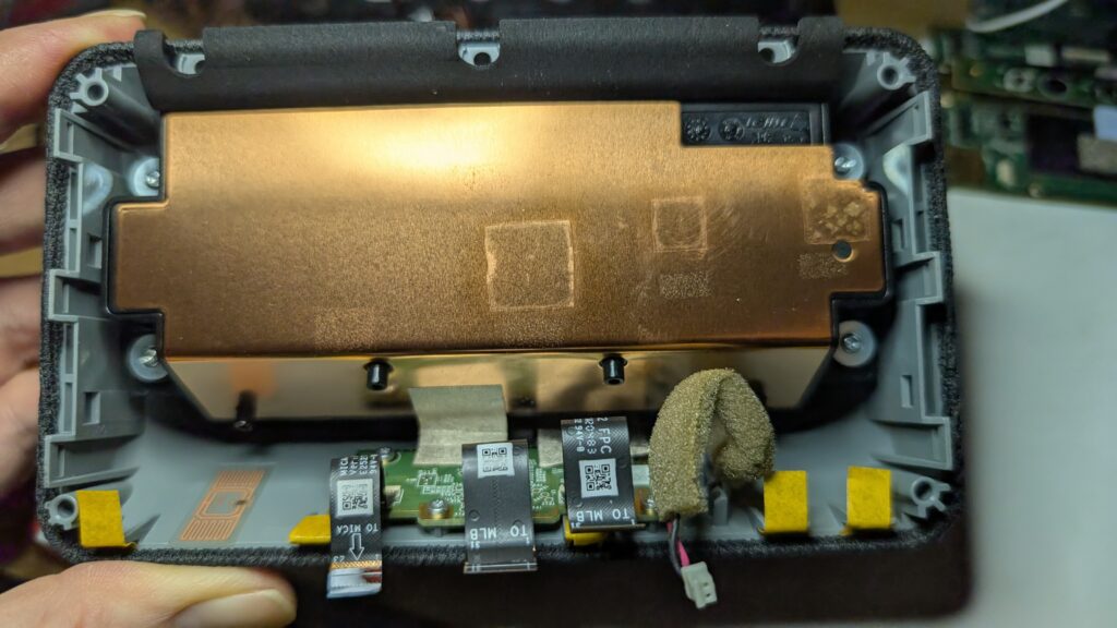
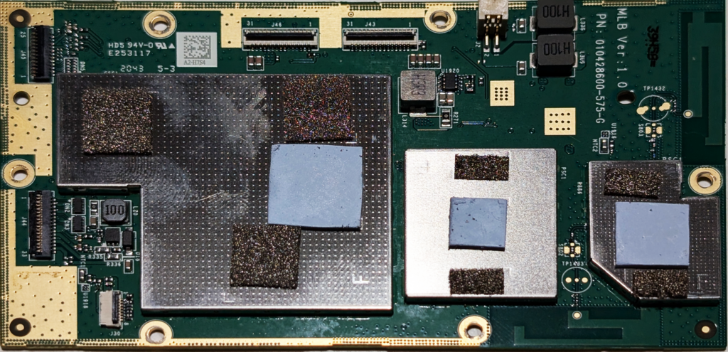
Removing these screws and popping open the casing to feast on the goo inside reveals the main board on one side, against the back of the screen.
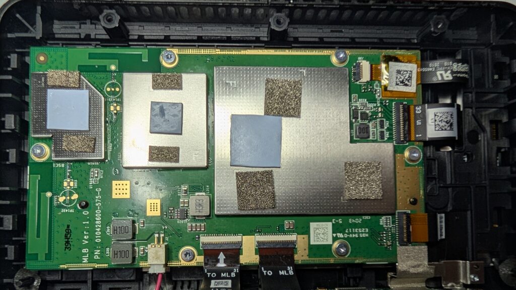
The main board is connected to the back of the casing via 2 ribbon cables and a single two-pin cable. One of the ribbon cables goes to a smaller board mounted on the bottom of the rear part of the case, and the other one goes behind the large, copper-covered block above it along with the two-pin cable. Another ribbon cable goes from the small board on the bottom of the rear part of the case to the top of the front part of the case.
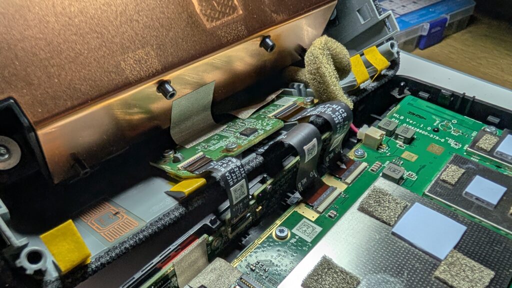
After popping these cables out, the screws holding the main board into the front of the case are the same T6 Torx type used on the outside of the case, albeit much shorter.
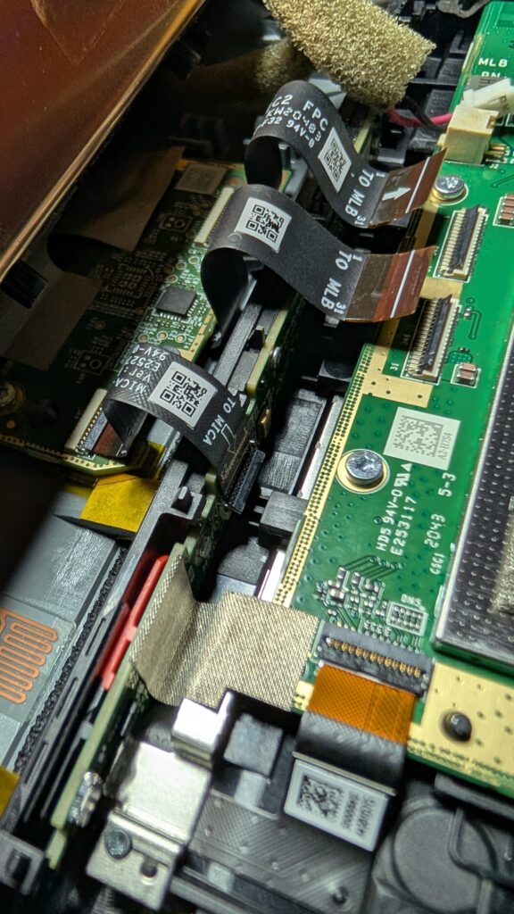
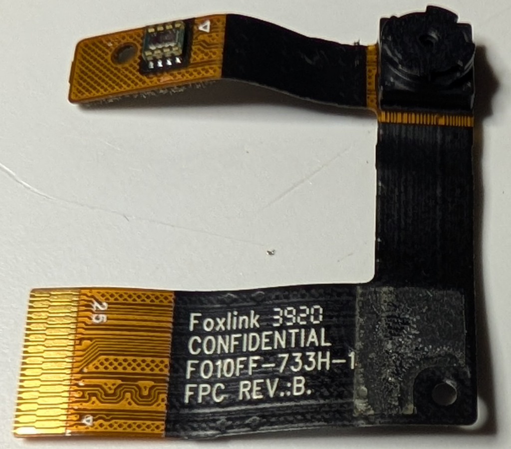
Moving to the side of the main board, there’s 3 more ribbon cables. 1 goes up to the top of the front of the case to the the camera module, and the other 2 appear to go behind the main board to the screen. 2 are the same kind of connector used on the top side of the main board, but the 3rd is slightly different with the locking mechanism being on the other side of the socket.
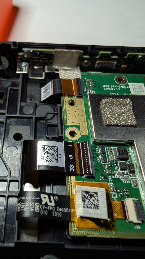
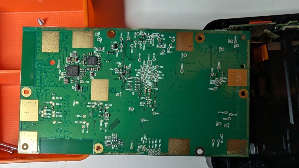
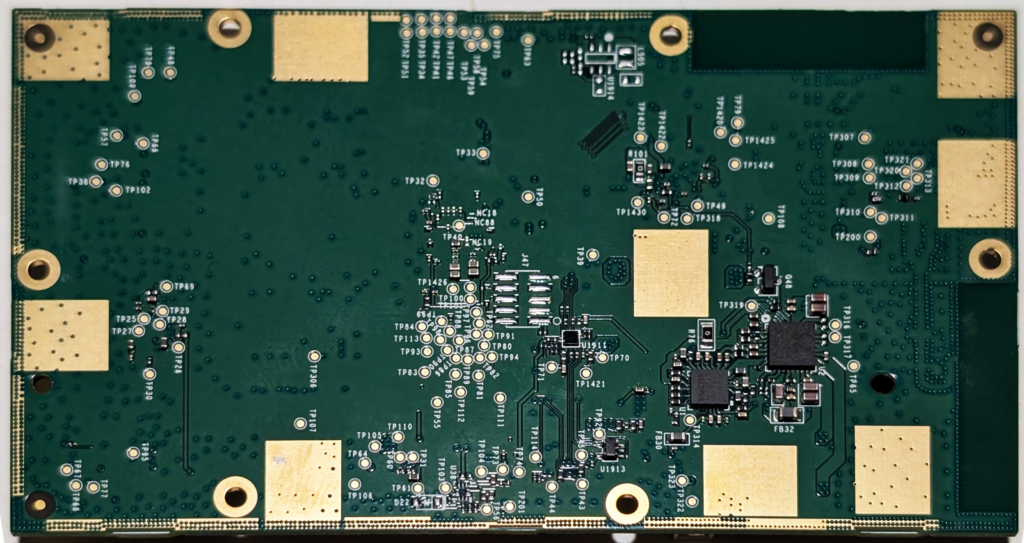
Disconnecting these ribbon cables allows us to pop the main board out of the front part of the case, getting a better look at it.
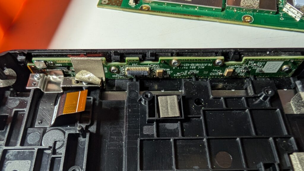
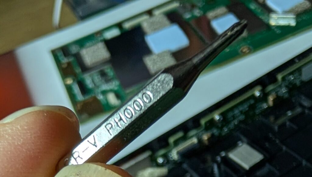
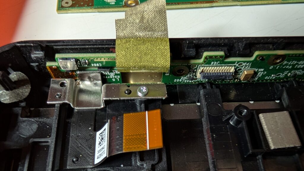
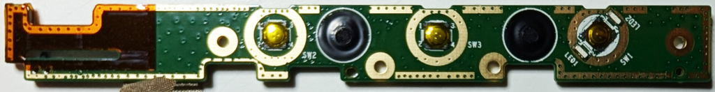
Moving to the top of the front part of the case, the small board across the top – which handles the buttons at the top of the device – is held in with small Philips-style screws. One of them is hidden under a piece of tape.
For reference, the screws appear to be a #000 size head.
The small metal piece is also lightly glued to the small board at the top, and will pop out with a bit of encouragement.
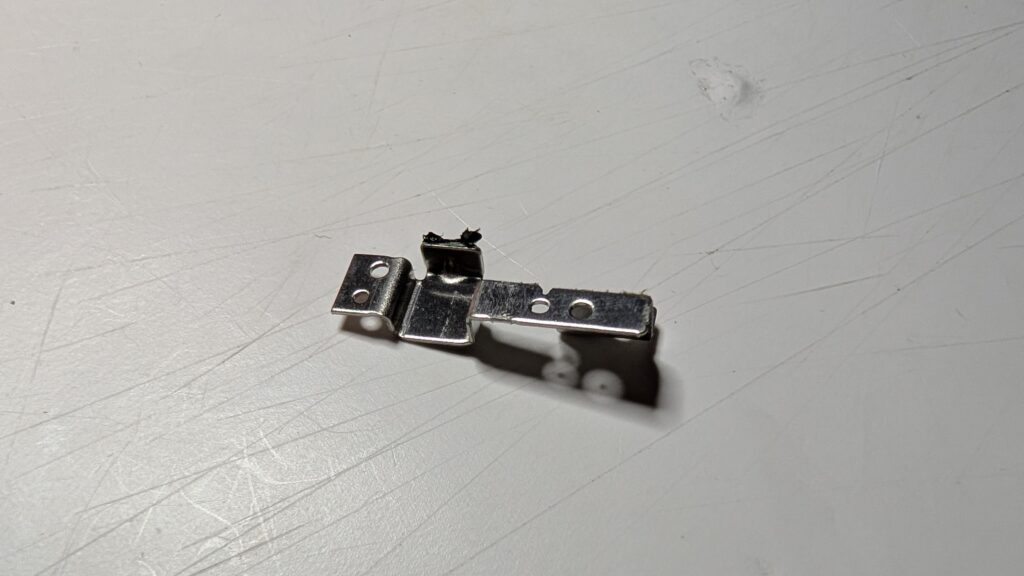
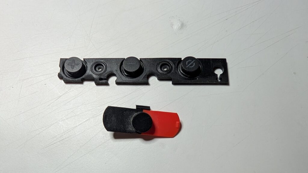
This leaves the small board free to come out too, along with the rubber button covers.
Poking in the rear
Moving to the rear part of the case, the large copper-covered block – which is the speaker – is held in again with T6 Torx screws, this time with wide heads.
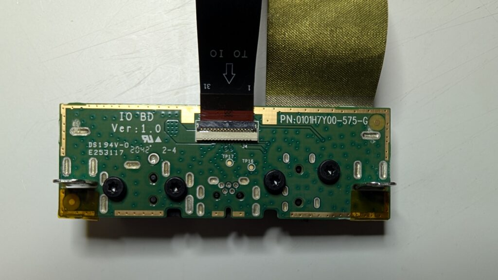
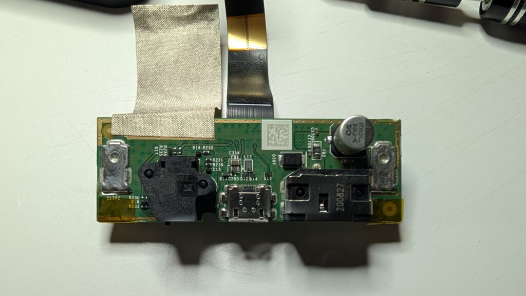
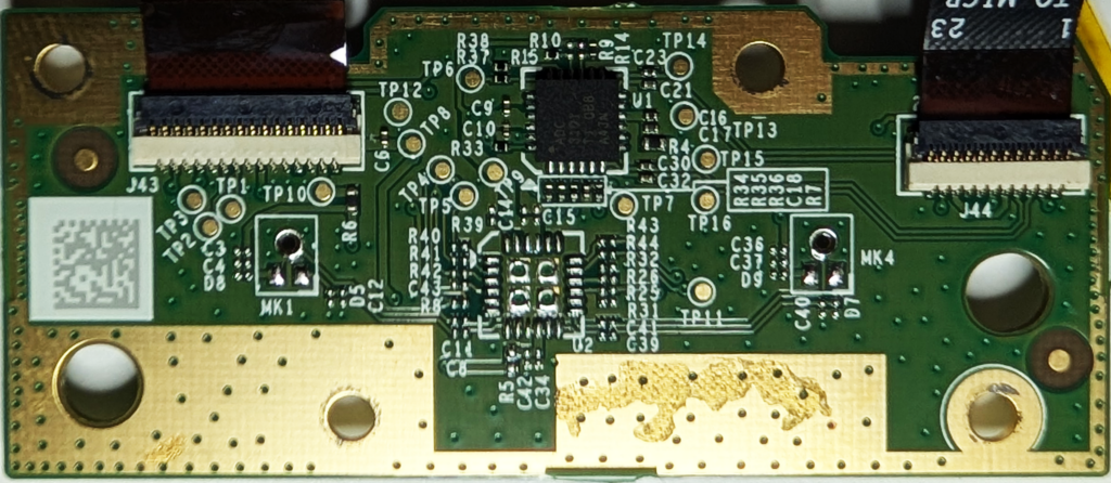
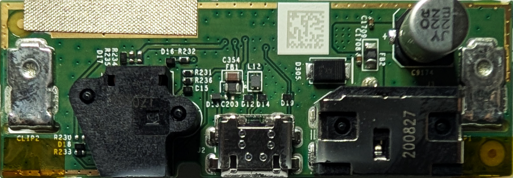
Removing these 4 screws allows the speaker to come out, revealing the final board. This handles the power, USB and external speaker connections.
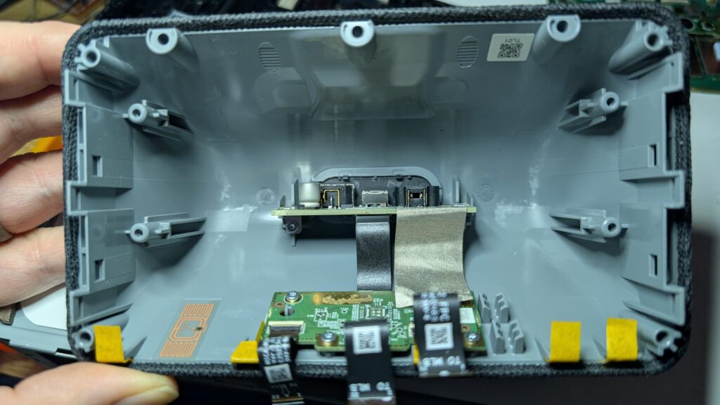
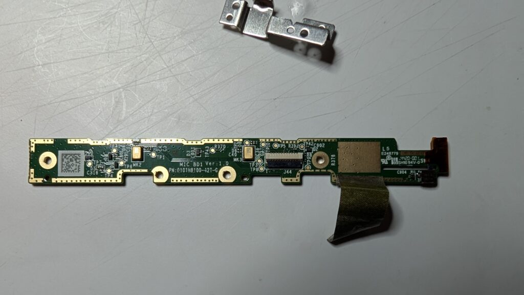
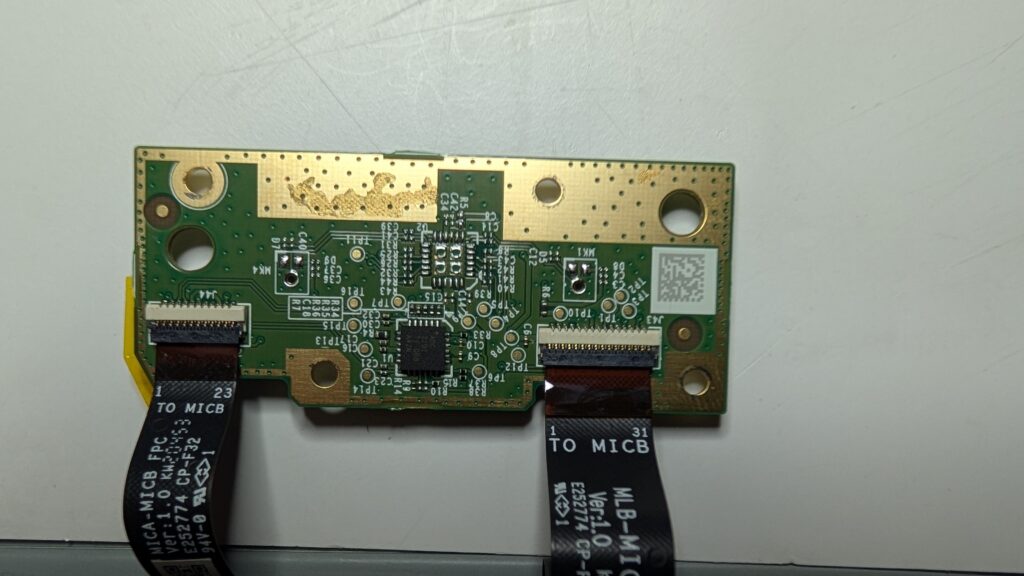
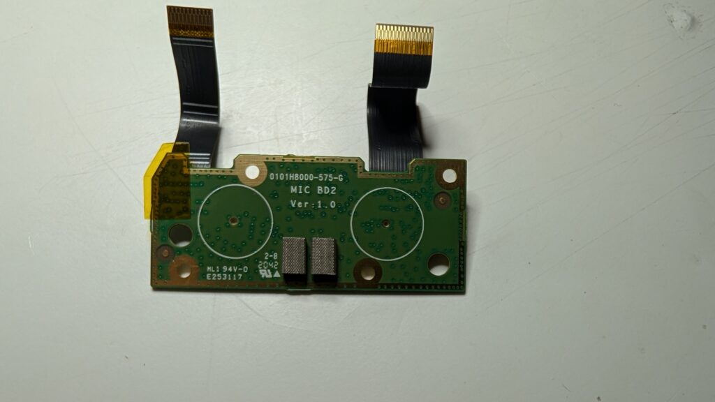
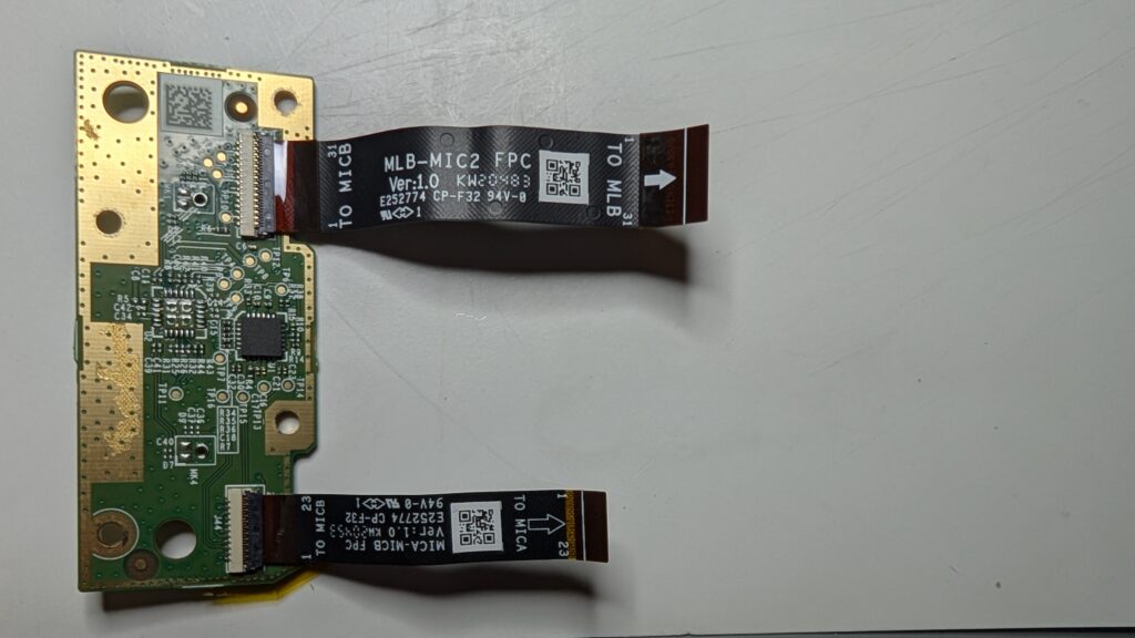
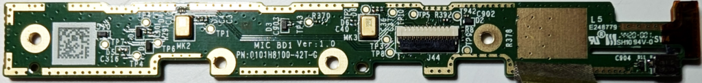
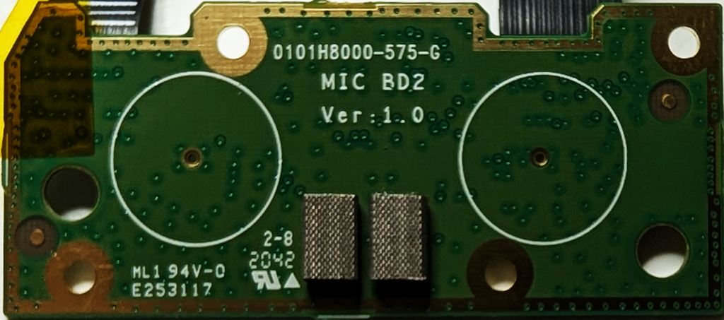
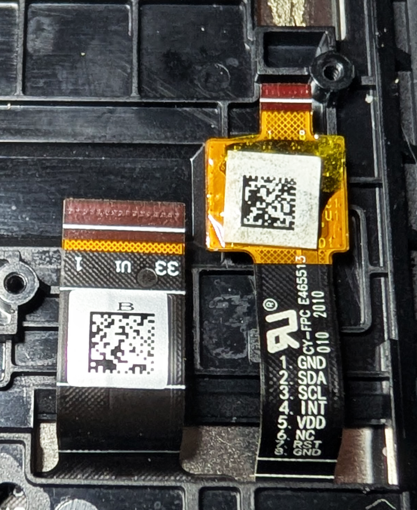
The board at the bottom of the case is again – you guessed it – held in with T6 Torx screws. This looks to be the microphones, based on the writing on the ribbon cables and the screen printing on the rear.
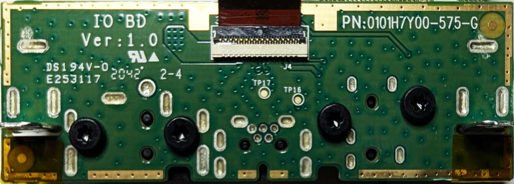
Our friend the T6 Torx is also holding in the connector board.
At this point we’ve basically disassembled the whole thing, however…
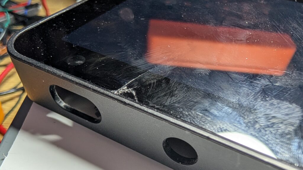
That bastard screen
As you’ve no doubt noticed, the screen is secured within the front part of the case. Unfortunately, the only way for it to come out is from the front, and the glass on the front is glued in. It will not come out without a fight and I gave up after narrowly avoiding firing a sliver of glass into my eye. You have been warned.
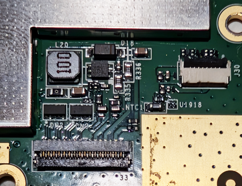
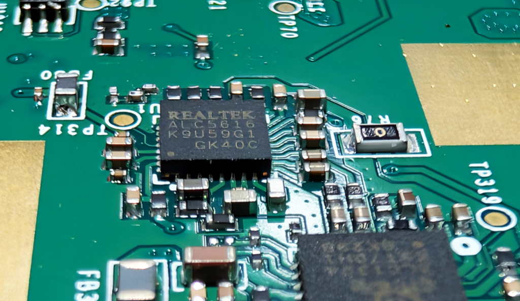
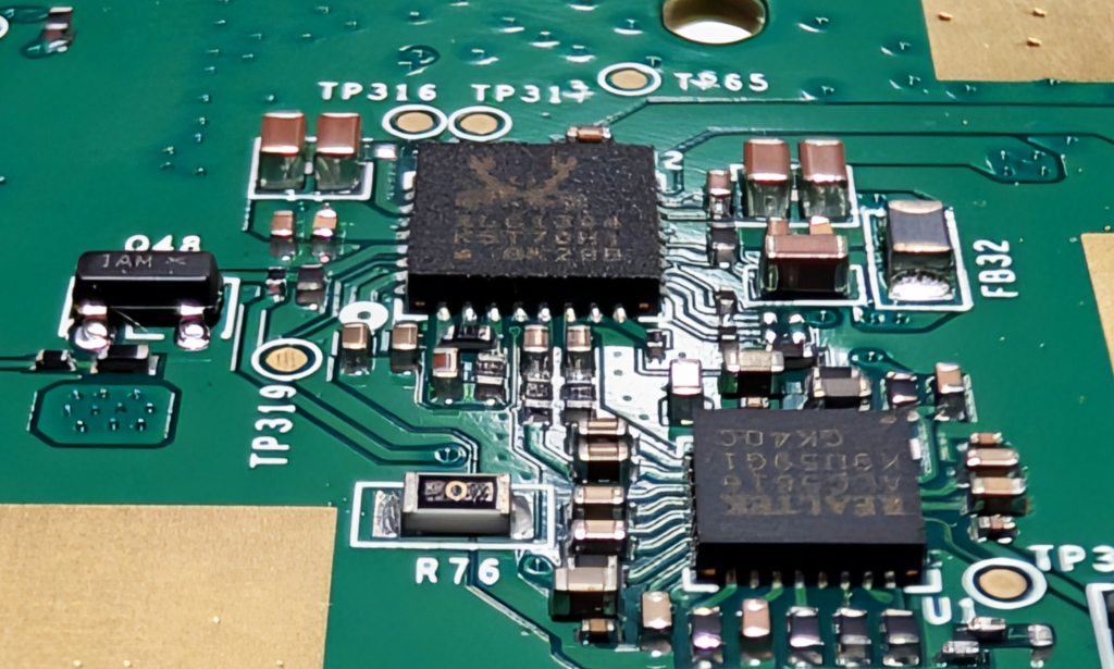
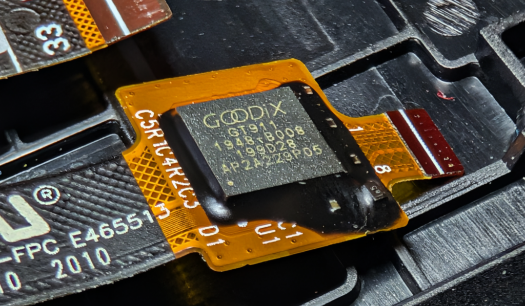
A closer look
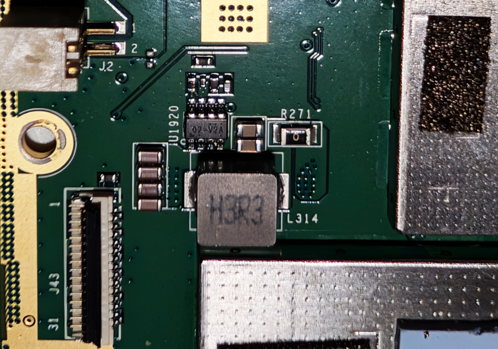
I don’t have any particular plans for the remains, but I did clean up some of the photos to make it easier to identify things.
Next steps
There’s some bits I’m thinking of salvaging from this, but that’s a topic for a future post. For now, this is sitting in my junk box – okay, who am I kidding, one of many of my junk boxes – until I remember it’s there.
Leave a Reply